The marketing promise on the box is seductive. “No Neutral Required,” it says, suggesting a five-minute swap where you trade an old toggle switch for a modern motion sensor. You turn off the breaker, cap the wires, screw it in, and restore power. Then the trouble starts.

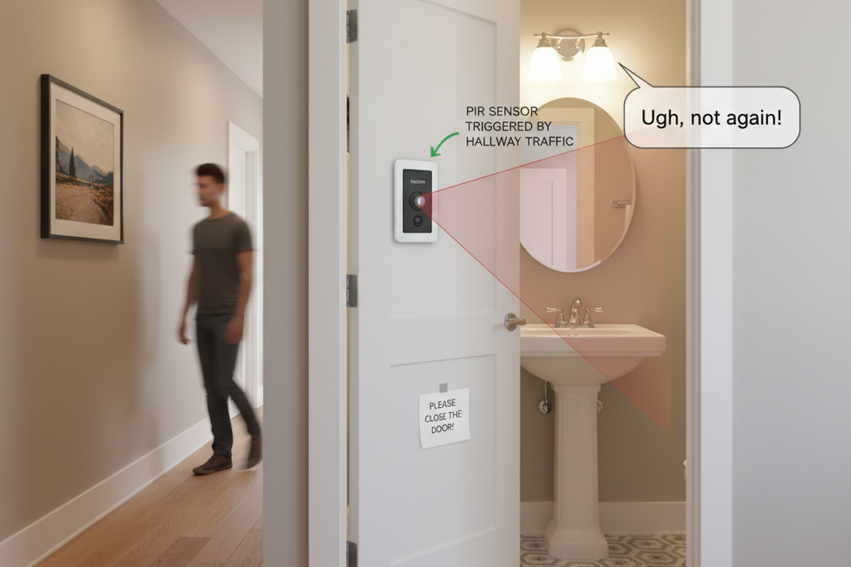
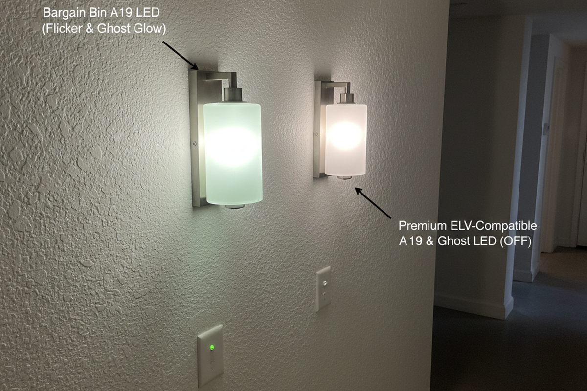
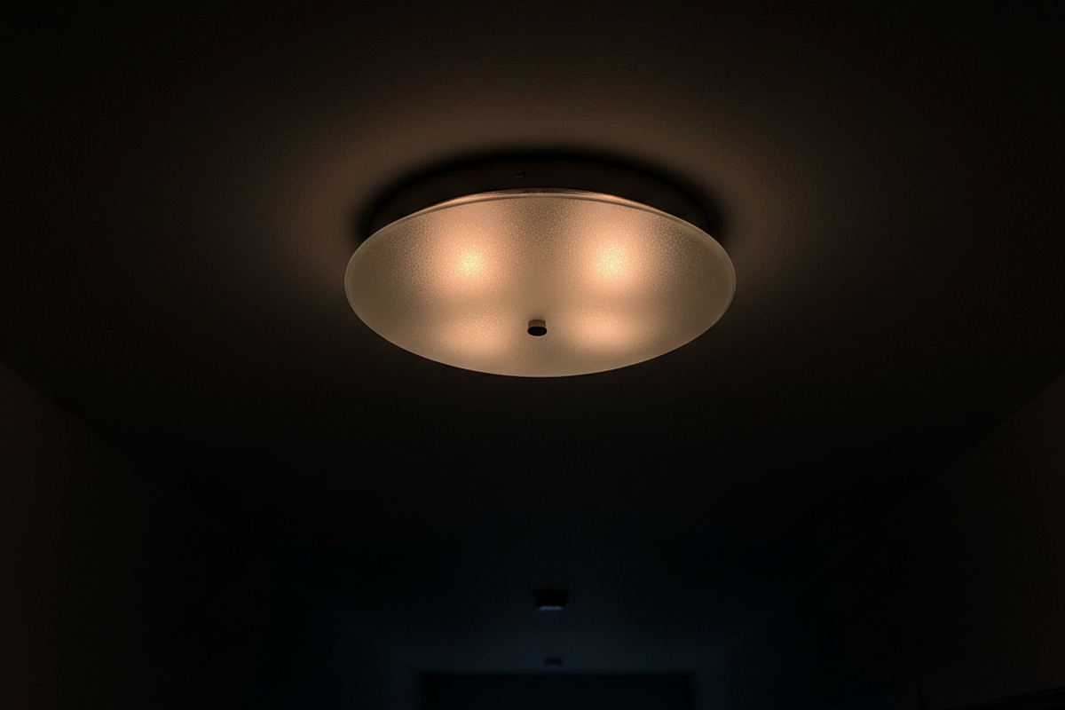
In the best-case scenario, the lights turn on but refuse to turn off completely, leaving a ghostly, dim glow in the fixture at 2 AM. In the worst case—often called the “Hallway Disco”—the sensor clicks frantically, strobing the lights like a rave until you kill the breaker. This isn’t a defective unit, nor is it a poltergeist in the wiring. It’s a fundamental conflict between 1970s wiring logic and the physics of modern LED drivers. The switch is starving for power, and it’s trying to eat through your light bulbs to survive.
The Leakage Current Reality
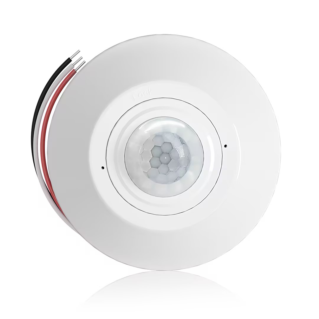
To understand why a Rayzeek RZ021 or similar sensor fails in an older home, you have to stop viewing the switch as a mechanical gate. Think of it as a computer. A standard toggle switch physically breaks the circuit; when it’s off, the wire is dead. A motion sensor, however, has a brain—an infrared detector and a logic chip—that needs to stay awake 24/7 to watch for movement.
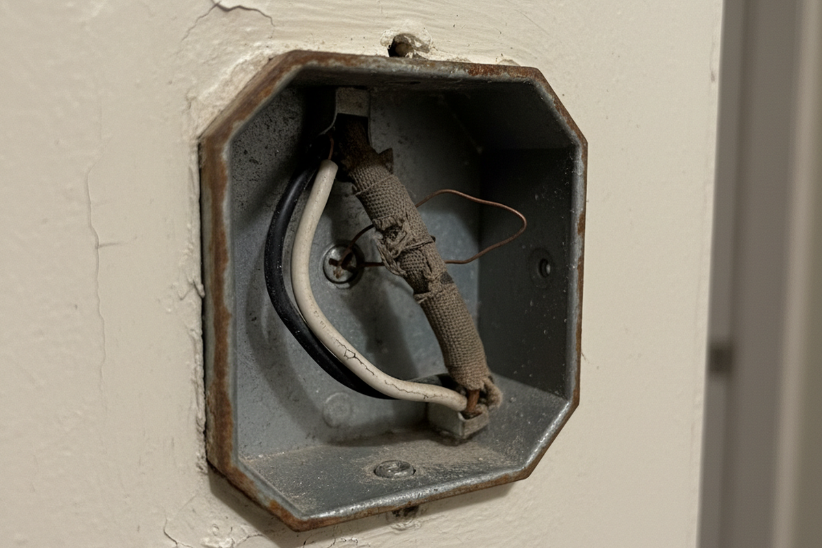
In a modern home (largely post-2011 NEC code), the box contains a white neutral wire. This provides a clean return path for the sensor’s operating current to cycle back to the panel without touching the lights. But in older switch loops, that white wire is missing or used as a traveler. The sensor still needs to complete its circuit to breathe, so it has only one option: send its operating current—the “leakage current”—out through the load wire, through the bulb’s filament, and back to the panel.
This worked beautifully in the era of incandescent bulbs. A 60-watt tungsten filament is a sturdy, dumb resistor. It lets that tiny trickle of current pass through without heating up enough to glow. The sensor gets its power, the bulb stays dark, and everyone is happy.
The problem arises when you replace that sturdy filament with a sensitive LED driver. LED bulbs aren’t simple resistors; they are complex electronic devices with capacitors that store energy. When the motion sensor sends its “leakage” current down the line, the LED’s capacitor catches it. It charges up, slowly and silently, until it hits its activation threshold. Pop—the light flashes on for a split second, dumping the energy. The capacitor drains, the light dies, and the cycle begins again. This is the heartbeat of the strobe effect. If you hear a buzzing sound coming from the fixture itself, that’s the audible frequency of the driver fighting this current—a clear signal that the components are mismatched.
The Minimum Load Math
You won’t find the solution in the switch settings. It’s a math problem. Every no-neutral sensor has a “Minimum Load Requirement,” often buried deep in the PDF datasheet. For many Rayzeek models, this floor is around 15 watts.
Maybe You Are Interested In
- Ceiling-mounted PIR occupancy sensor with dry-contact relay output
- 12/24VDC or 12/24VAC low-voltage supply
- COM, NO, and NC isolated relay contacts for EMS, HVAC, and building control inputs
- Low-voltage DC recessed ceiling-mounted microwave motion sensor switch
- 12 VDC / 24 VDC input with 10-30 VDC range
- 10A max work current with adjustable time delay, Lux threshold, and sensitivity
- Higher-load recessed ceiling-mounted microwave motion sensor switch
- 100-265 VAC line-voltage input, 10A model
- 5.8 GHz microwave sensing with adjustable time delay, Lux threshold, and sensitivity
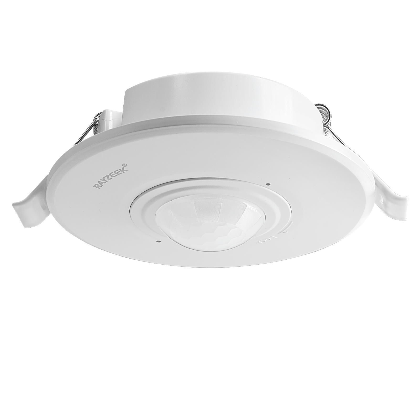
- Recessed ceiling-mounted microwave motion sensor switch
- 100-265 VAC line-voltage input, 5A model
- 5.8 GHz microwave sensing with adjustable time delay, Lux threshold, and sensitivity
- Ceiling-mounted RZ037 PIR occupancy sensor dimmer for 220V power
- 3A maximum working current with 660W rated load
- LUX button controls light-sensor ON/OFF and user-set dimming brightness
- Ceiling-mounted RZ037 PIR occupancy sensor dimmer for 110V power
- 3A maximum working current with 330W rated load
- LUX button controls light-sensor ON/OFF and user-set dimming brightness
- Low-voltage DC ceiling-mounted microwave motion sensor switch
- 12 VDC / 24 VDC input with 10-30 VDC range
- 10A max work current with adjustable time delay, Lux threshold, and sensitivity
- Higher-load ceiling-mounted microwave motion sensor switch
- 100-265 VAC line-voltage input, 10A model
- 5.8 GHz microwave sensing with adjustable time delay, Lux threshold, and sensitivity
- Ceiling-mounted microwave motion sensor switch
- 100-265 VAC line-voltage input, 5A model
- 5.8 GHz microwave sensing with adjustable time delay, Lux threshold, and sensitivity
- Low-voltage DC recessed ceiling mount PIR motion sensor switch
- 12 VDC / 24 VDC input with 10-30 VDC range
- Max work current 10A with adjustable time delay, Lux threshold, and sensitivity
- Higher-load recessed ceiling mount PIR motion sensor switch
- 100-265 VAC line-voltage input, 10A model
- 360-degree detection with adjustable time delay, Lux threshold, and sensitivity
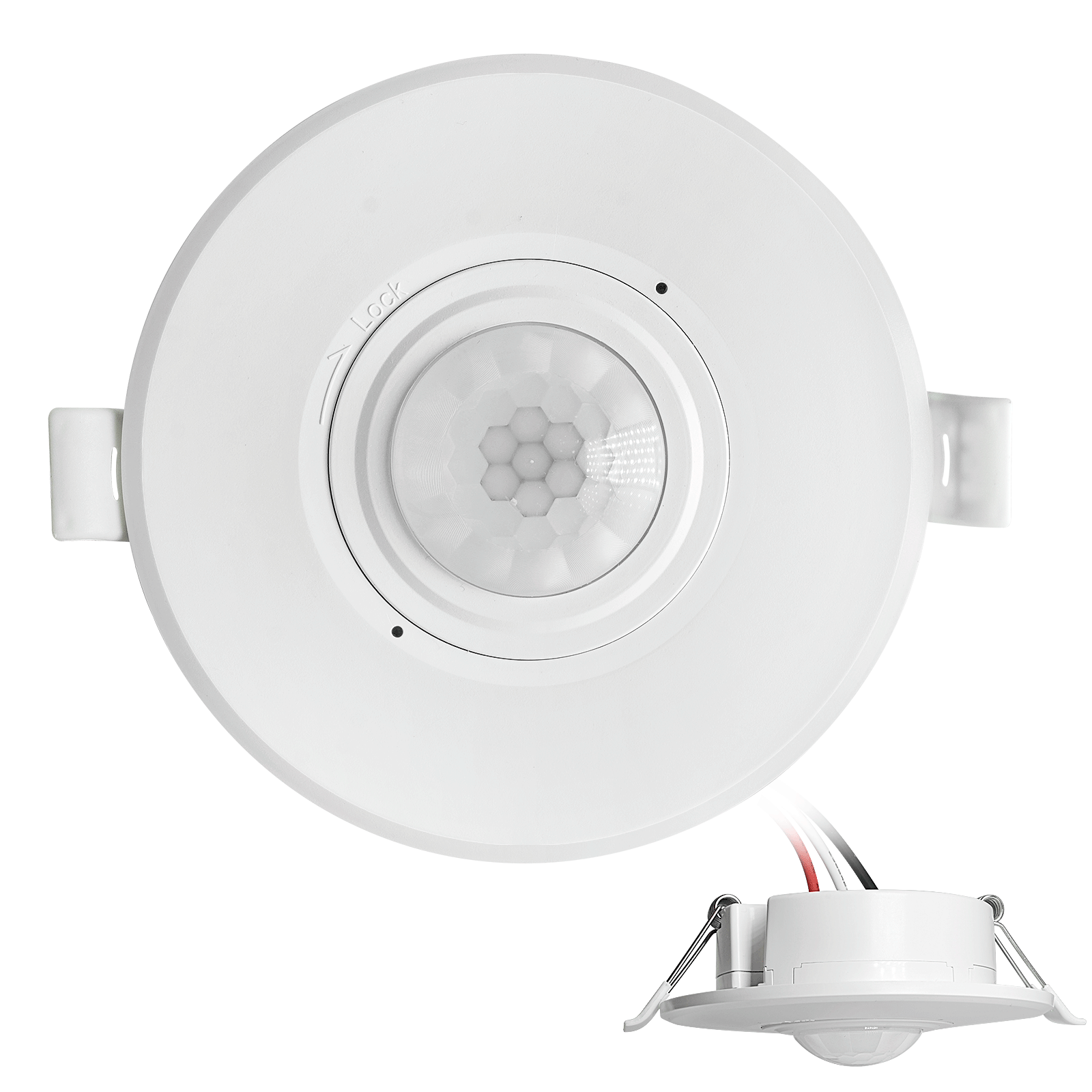
- Recessed ceiling mount PIR motion sensor switch
- 100-265 VAC line-voltage input, 5A model
- 360-degree detection with adjustable time delay, Lux threshold, and sensitivity
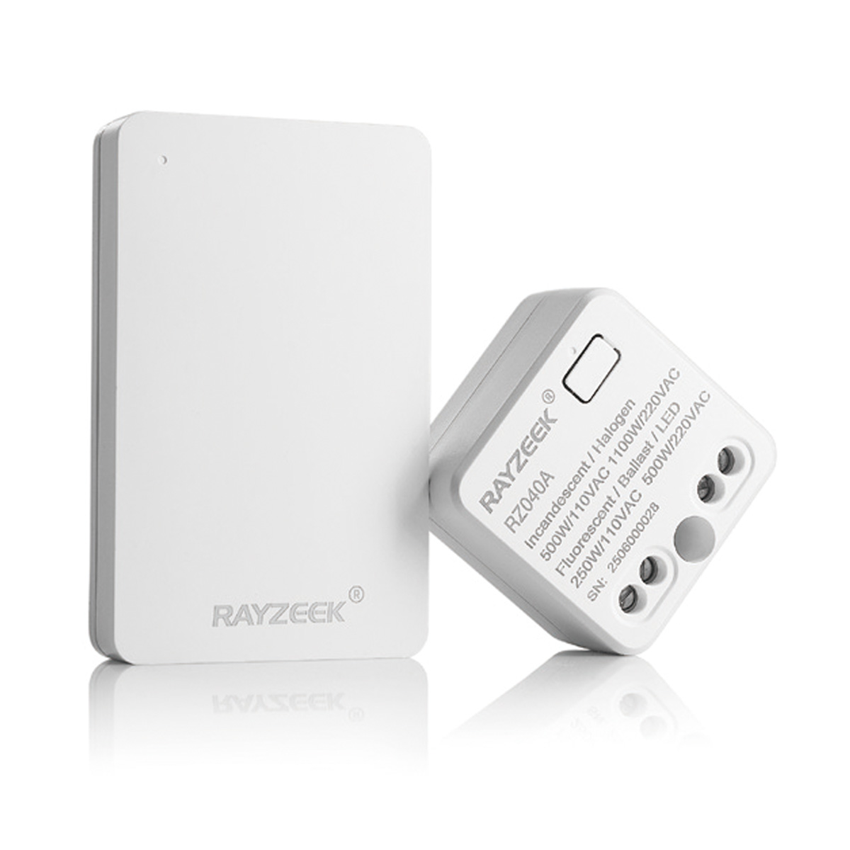
- Wireless switch and receiver kit for indoor ON/OFF lighting control
- 100-230VAC, 50/60Hz receiver with 5A rated current
- CR2032-powered wireless switch with 2.4GHz communication
- Occupancy (Auto-ON/Auto-OFF)
- 12–24V DC (10–30VDC), up to 10A
- 360° coverage, 8–12 m diameter
- Time delay 15 s–30 min
- Light sensor Off/15/25/35 Lux
- High/Low sensitivity
- Auto-ON/Auto-OFF occupancy mode
- 100–265V AC, 10A (neutral required)
- 360° coverage; 8–12 m detection diameter
- Time delay 15 s–30 min; Lux OFF/15/25/35; Sensitivity High/Low
- Auto-ON/Auto-OFF occupancy mode
- 100–265V AC, 5A (neutral required)
- 360° coverage; 8–12 m detection diameter
- Time delay 15 s–30 min; Lux OFF/15/25/35; Sensitivity High/Low
- 100V-230VAC
- Transmission Distance: up to 20m
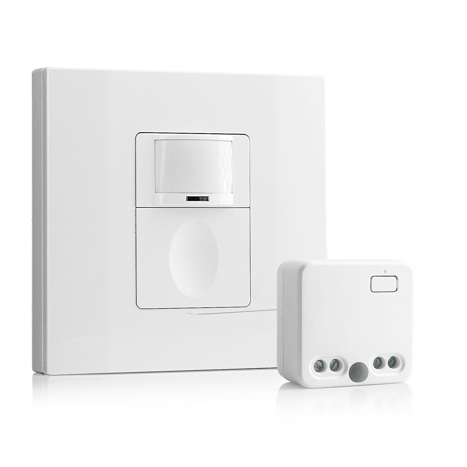
- Wireless motion sensor
- Hardwired control
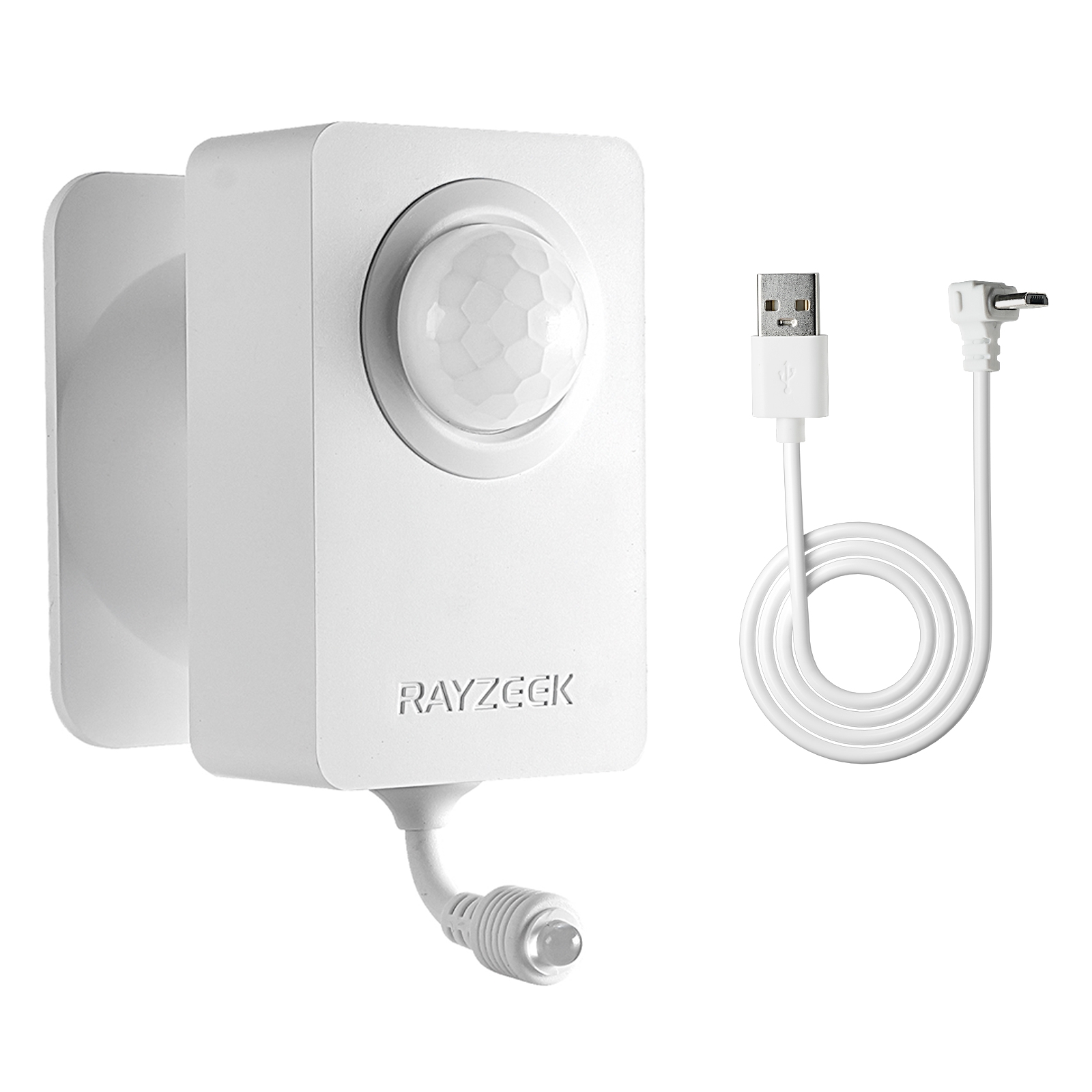
- Voltage: 2x AAA Batteries / 5V DC (Micro USB)
- Day/Night Mode
- Time delay: 15min, 30min, 1h(default), 2h
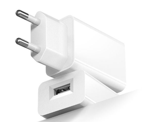
- EU plug power adapter
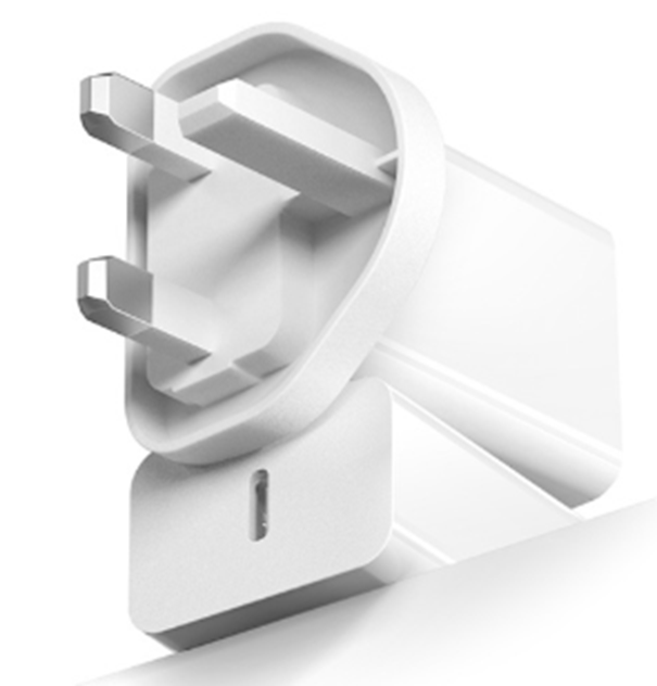
- UK plug power adapter
In the age of efficiency, hitting 15 watts is harder than it sounds. A single generic LED bulb might draw 4 watts. A fancy vintage-style Edison LED might draw only 2.5. If a hallway fixture has two of these bulbs, the total load is 5 to 8 watts—well below the threshold required to stabilize the current. The sensor tries to pull power, the load is too light to anchor it, and the internal relay starts clicking. It sounds like a turn signal in a car that won’t start.
This is where the “Bulb Lottery” comes into play. Not all LEDs are created equal. Brands like Philips and Cree often build better damping into their dimmable drivers, allowing them to tolerate the leakage current without ghosting. Conversely, budget brands found in the checkout aisle of a hardware store—Feit Electric or the unbranded bulk packs—often lack this regulation. They are efficient, but fragile. A sensor that works perfectly with a 10-watt Cree bulb might strobe uncontrollably with a 10-watt generic bulb simply because the driver architecture is different. And since manufacturers change internal components without changing the model number, a bulb that worked last year might not work this year.
Looking For Motion-Activated Energy-Saving Solutions?
Contact us for complete PIR motion sensors, motion-activated energy-saving products, motion sensor switches, and Occupancy/Vacancy commercial solutions.
The Bypass Fix

When the math doesn’t work and the bulbs are flickering, there is a brute-force solution that preserves the sensor without rewiring the house: the bypass capacitor.
Often sold as a “dynamic load adapter” or under part numbers like the Lutron LUT-MLC, this small component is the secret weapon for no-neutral installs. It’s not a battery; it’s a dummy load. You install it not at the switch, but up at the light fixture itself, wiring it in parallel between the hot and neutral wires inside the canopy.
The bypass acts as a pressure valve. It provides a dedicated path for that leakage current to go around the sensitive LED bulbs. The sensor gets its power through the capacitor, the LEDs stay dark until actually turned on, and the flickering stops. It feels like a hack—adding a “useless” part to a circuit—but in a no-neutral environment, it is often the difference between a working smart home and a fire hazard.
Wiring the Ground
There is a final, uncomfortable reality regarding the Rayzeek RZ021 and similar units: the role of the green wire. In a strictly code-compliant world, current should never flow on the grounding conductor. The ground is for safety, not for returning power to the panel.
Get Inspired by Rayzeek Motion Sensor Portfolios.
Doesn't find what you want? Don't worry. There are always alternate ways to solve your problems. Maybe one of our portfolios can help.
However, many no-neutral sensors are engineered to cheat this rule slightly. They use the ground wire as a reference point to stabilize their internal electronics. If you open a 1950s metal switch box and see only two black wires and the bare metal of the box, you might be tempted to leave the green wire on the sensor disconnected. Don’t do it. Without that ground reference, the sensor’s brain often floats electrically, leading to erratic detection or a failure to energize.
If your home uses armored cable (BX) or metal conduit, the box itself is the ground. You must bond the sensor’s green wire to the box. If you have older Romex with a bare copper wire, that must be connected. It is a compromise—using the safety drain for a tiny amount of operational stability—but it is how these specific units are designed to function. If you are uncomfortable with current on the ground, the only code-perfect solution is to pull a new neutral wire, a job that involves tearing open drywall and spending thousands.
Knowing When to Fold
Sometimes, the physics wins. If you are trying to control a single 3-watt LED tape light in a pantry, or a specialized low-voltage fixture, no amount of bypass capacitors or expensive bulbs will stabilize a high-voltage no-neutral sensor. The load is simply too small.
In these cases, the correct move is to stop fighting the wiring. Cap the wires, put a standard toggle switch back in (or wire it always-on), and buy a battery-powered motion sensor like a Philips Hue or a generic Zigbee device paired with a smart bulb. It lacks the permanence of a hardwired switch, and you will have to change batteries every two years, but it separates the control logic from the power delivery. In a house fighting against 50-year-old wiring constraints, that separation is sometimes the only way to keep the lights off at 3 AM.