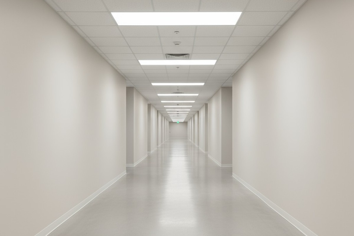
It’s a familiar experience in self-storage facilities and buildings with long, featureless hallways. A customer pushes a cart into a dark corridor, and the lights snap on a moment too late, either directly overhead or, worse, just behind them. They are forced to constantly push forward into darkness, creating a perpetual feeling of being one step behind. It’s a small design failure that creates a significant sense of unease and cheapness. The solution isn’t to make existing systems more sensitive, but to make them more intelligent.
This problem of “light lag” can be solved permanently with a systematic approach that transforms a building’s lighting from a reactive system to an anticipatory one. By carefully planning sensor placement, aiming, and timing, you can create a seamless experience where the path is always lit well before a person arrives, guiding them forward as if by an invisible hand. This method ensures customers never have to push their cart into darkness again.
The Common Corridor Problem: Chasing the Light
In a standard motion-activated system, a single sensor controls a dedicated zone of lights. When a person enters that zone, the sensor detects motion and switches on the fixtures. In a long corridor, this creates a disjointed experience of moving from one pool of light to the next. The system is always reacting to presence, not anticipating intent. As a result, the user is perpetually at the edge of the detection zone, triggering the light just as they arrive and forcing them to “chase the light” down the hallway—a constant reminder that the system is lagging.
The Sensitivity Trap: Why Turning Up the Dial Causes More Problems
The most common reaction to light lag is to increase the sensitivity of the motion sensors. The logic seems sound: a more sensitive sensor should detect motion from farther away and activate the lights sooner. In practice, this approach often backfires and introduces new issues.
False Triggers from Cross-Corridor Traffic
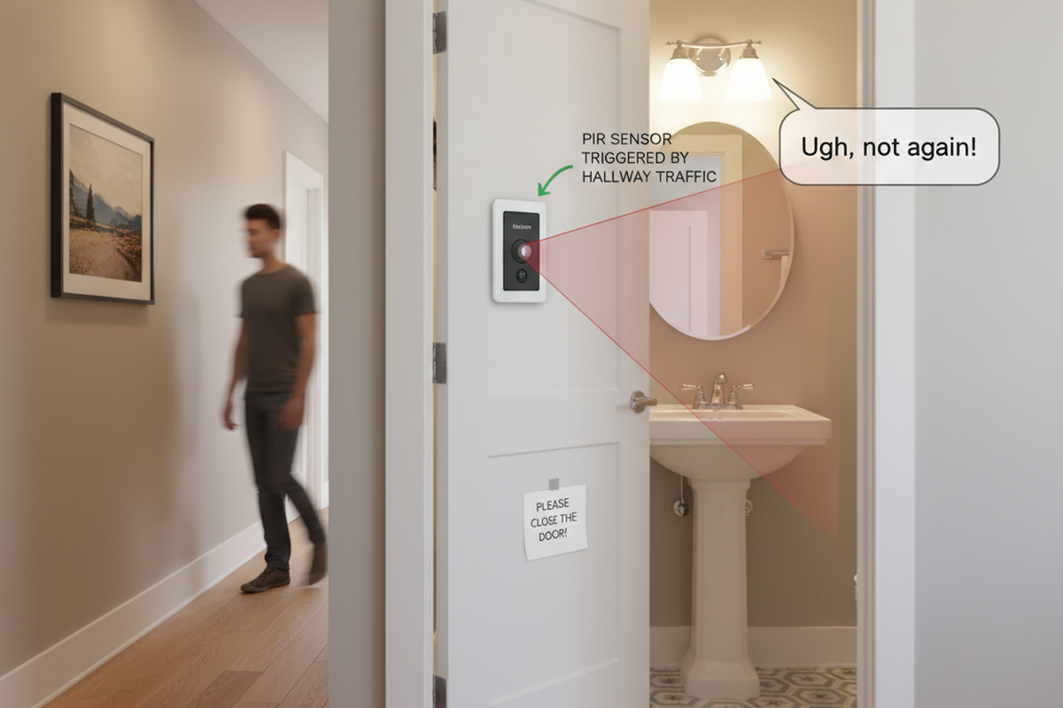
High-sensitivity settings make sensors, especially Passive Infrared (PIR) types, highly susceptible to detecting motion outside their intended zone. In a self-storage facility, this means someone walking down a main thoroughfare can trigger lights in an intersecting corridor they have no intention of entering. This cross-corridor activation wastes energy and creates a distracting “light show” effect, with empty hallways constantly turning on and off. The system becomes noisy and inefficient, solving one problem by creating another.
The Diminishing Returns of High Sensitivity
Beyond a certain point, increasing sensitivity yields no benefit for early detection down a long, narrow path. A sensor’s ability to detect motion is a function of its lens design and the nature of the movement. Motion directly toward or away from a PIR sensor is inherently harder to detect than motion that crosses its field of view. Cranking the sensitivity doesn’t change this fundamental limitation; it only makes the sensor better at picking up small, tangential movements—often the very source of false triggers. The core problem of detecting forward motion at a distance remains unsolved.
The Foundational Principle: From Reaction to Anticipation
If turning up the sensitivity isn’t the answer, what is? The solution requires a shift in thinking: instead of trying to make a reactive system faster, the goal is to design an anticipatory system that uses geometry and logic to predict a user’s path. The lighting should not be a response to where the person is, but a preparation for where they are going. This is achieved through three coordinated principles: spacing, aiming, and temporal logic.
Pillar 1: Geometric Spacing and the Staggered Sensor Layout
A single sensor, no matter how powerful, is a single point of failure with a limited detection zone. The key to effective corridor coverage is using multiple sensors in an arrangement that creates continuous, overlapping fields of view. The most effective geometry for this is a staggered layout. Instead of placing sensors in a straight line down the center of the corridor, they are alternated from one side of the hallway to the other.
Maybe You Are Interested In
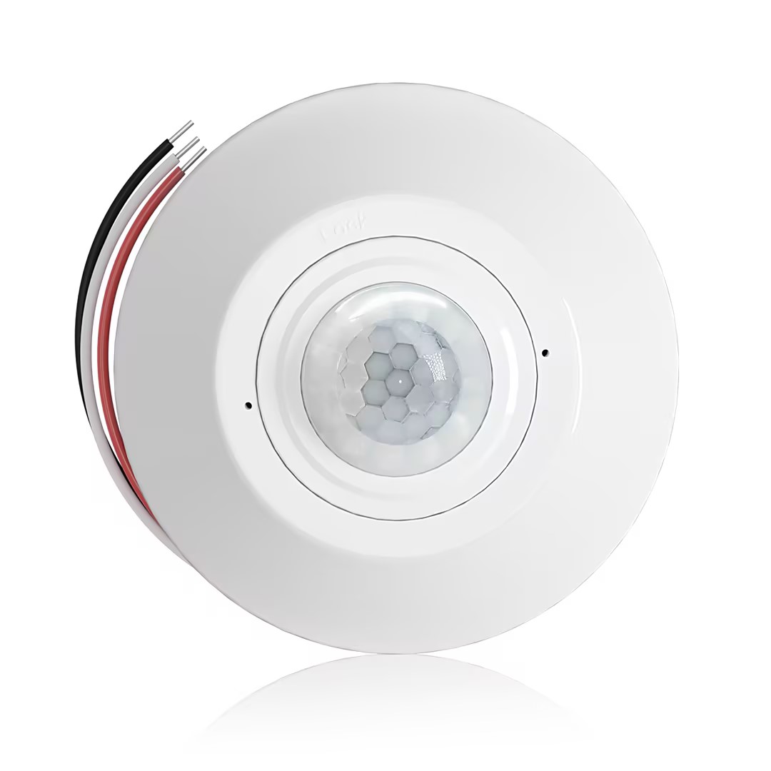
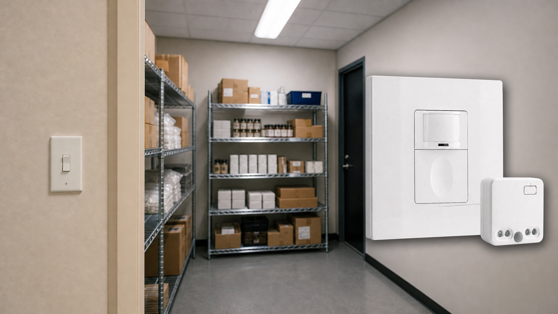
- Ceiling-mounted PIR occupancy sensor with dry-contact relay output
- 12/24VDC or 12/24VAC low-voltage supply
- COM, NO, and NC isolated relay contacts for EMS, HVAC, and building control inputs
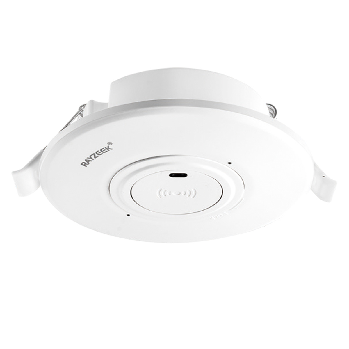
- Low-voltage DC recessed ceiling-mounted microwave motion sensor switch
- 12 VDC / 24 VDC input with 10-30 VDC range
- 10A max work current with adjustable time delay, Lux threshold, and sensitivity
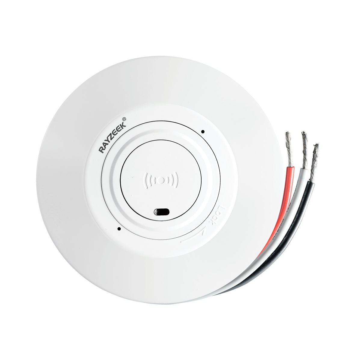
- Higher-load recessed ceiling-mounted microwave motion sensor switch
- 100-265 VAC line-voltage input, 10A model
- 5.8 GHz microwave sensing with adjustable time delay, Lux threshold, and sensitivity
- Recessed ceiling-mounted microwave motion sensor switch
- 100-265 VAC line-voltage input, 5A model
- 5.8 GHz microwave sensing with adjustable time delay, Lux threshold, and sensitivity
- Ceiling-mounted RZ037 PIR occupancy sensor dimmer for 220V power
- 3A maximum working current with 660W rated load
- LUX button controls light-sensor ON/OFF and user-set dimming brightness
- Ceiling-mounted RZ037 PIR occupancy sensor dimmer for 110V power
- 3A maximum working current with 330W rated load
- LUX button controls light-sensor ON/OFF and user-set dimming brightness
- Low-voltage DC ceiling-mounted microwave motion sensor switch
- 12 VDC / 24 VDC input with 10-30 VDC range
- 10A max work current with adjustable time delay, Lux threshold, and sensitivity
- Higher-load ceiling-mounted microwave motion sensor switch
- 100-265 VAC line-voltage input, 10A model
- 5.8 GHz microwave sensing with adjustable time delay, Lux threshold, and sensitivity
- Ceiling-mounted microwave motion sensor switch
- 100-265 VAC line-voltage input, 5A model
- 5.8 GHz microwave sensing with adjustable time delay, Lux threshold, and sensitivity
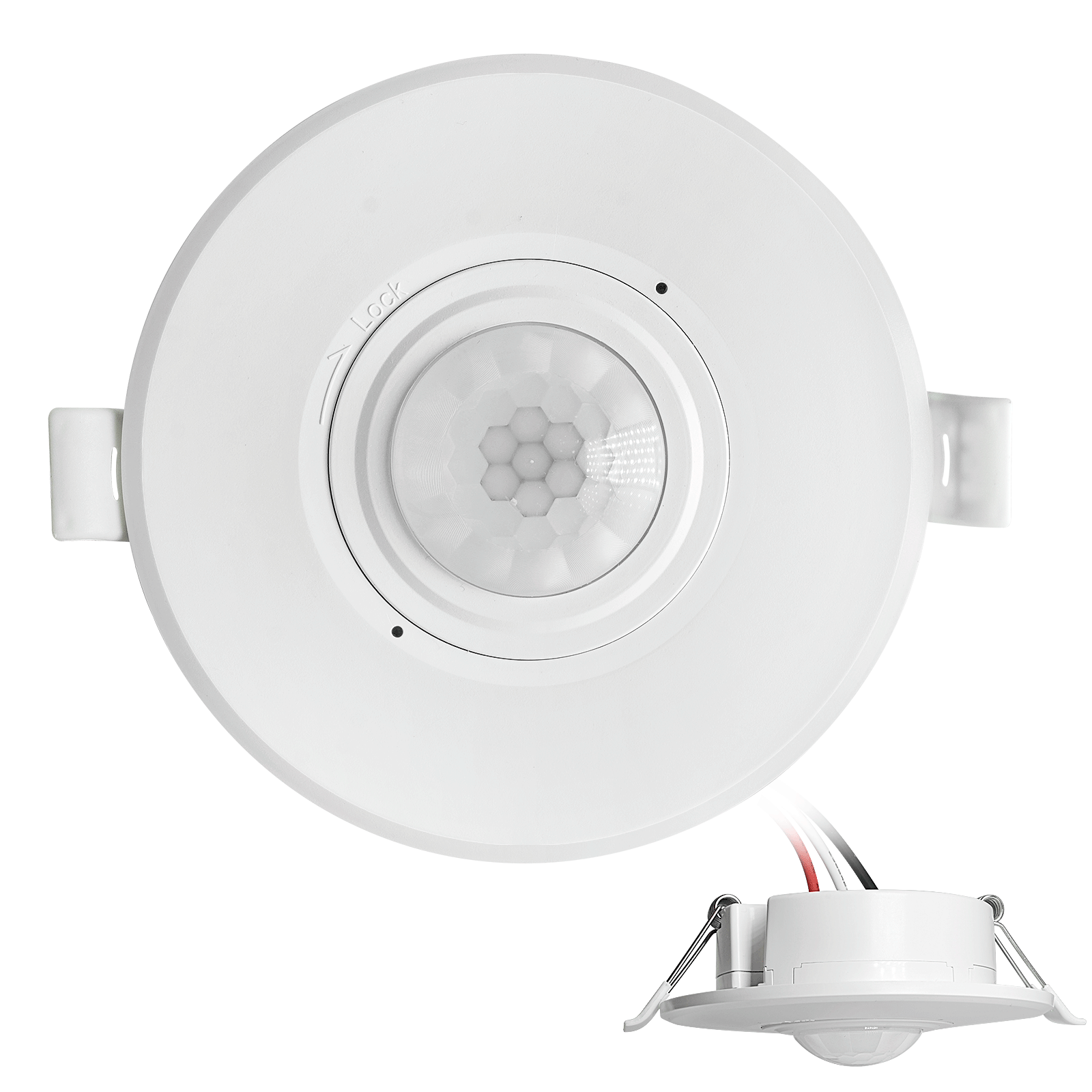
- Low-voltage DC recessed ceiling mount PIR motion sensor switch
- 12 VDC / 24 VDC input with 10-30 VDC range
- Max work current 10A with adjustable time delay, Lux threshold, and sensitivity
- Higher-load recessed ceiling mount PIR motion sensor switch
- 100-265 VAC line-voltage input, 10A model
- 360-degree detection with adjustable time delay, Lux threshold, and sensitivity
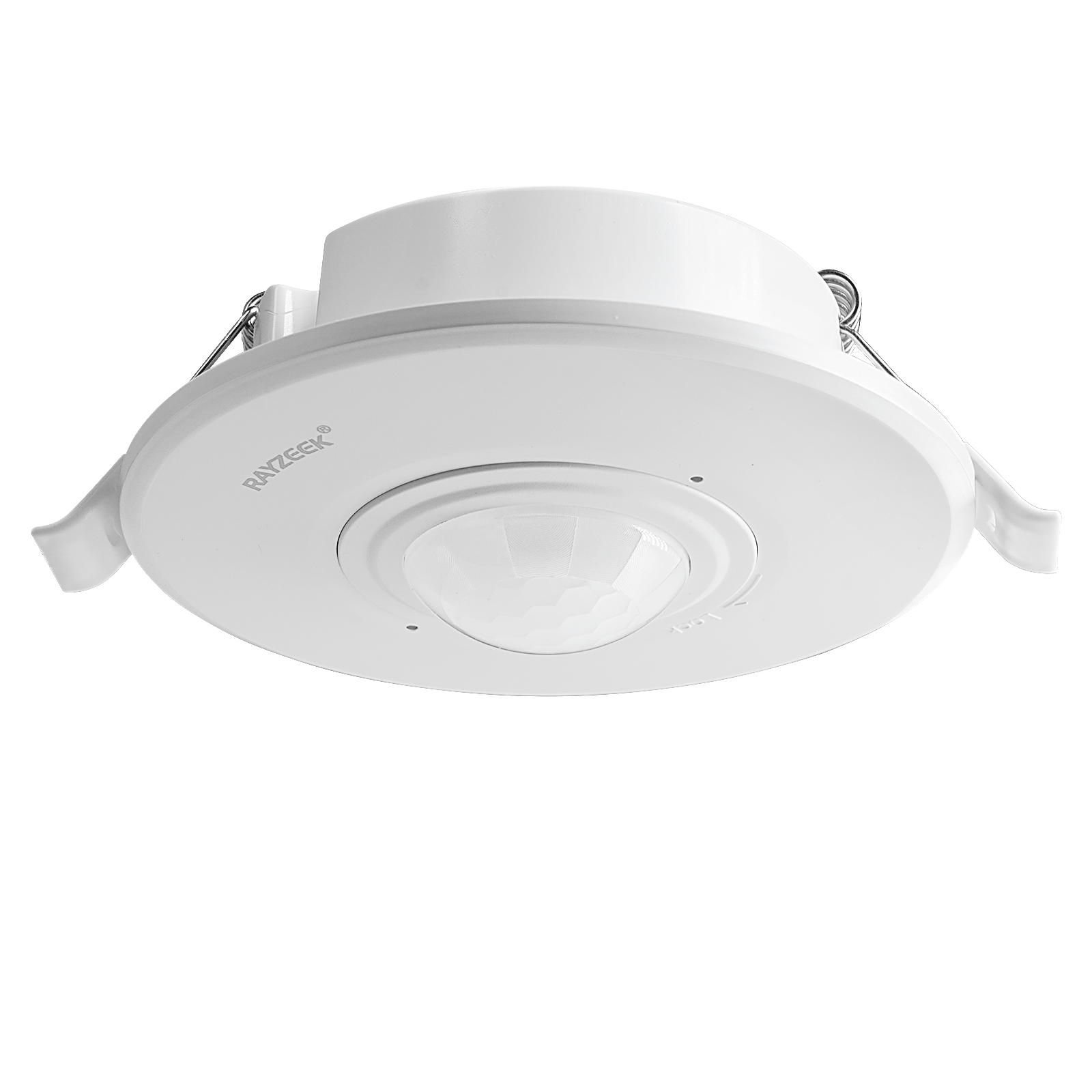
- Recessed ceiling mount PIR motion sensor switch
- 100-265 VAC line-voltage input, 5A model
- 360-degree detection with adjustable time delay, Lux threshold, and sensitivity
- Wireless switch and receiver kit for indoor ON/OFF lighting control
- 100-230VAC, 50/60Hz receiver with 5A rated current
- CR2032-powered wireless switch with 2.4GHz communication
- Occupancy (Auto-ON/Auto-OFF)
- 12–24V DC (10–30VDC), up to 10A
- 360° coverage, 8–12 m diameter
- Time delay 15 s–30 min
- Light sensor Off/15/25/35 Lux
- High/Low sensitivity
- Auto-ON/Auto-OFF occupancy mode
- 100–265V AC, 10A (neutral required)
- 360° coverage; 8–12 m detection diameter
- Time delay 15 s–30 min; Lux OFF/15/25/35; Sensitivity High/Low
- Auto-ON/Auto-OFF occupancy mode
- 100–265V AC, 5A (neutral required)
- 360° coverage; 8–12 m detection diameter
- Time delay 15 s–30 min; Lux OFF/15/25/35; Sensitivity High/Low
- 100V-230VAC
- Transmission Distance: up to 20m
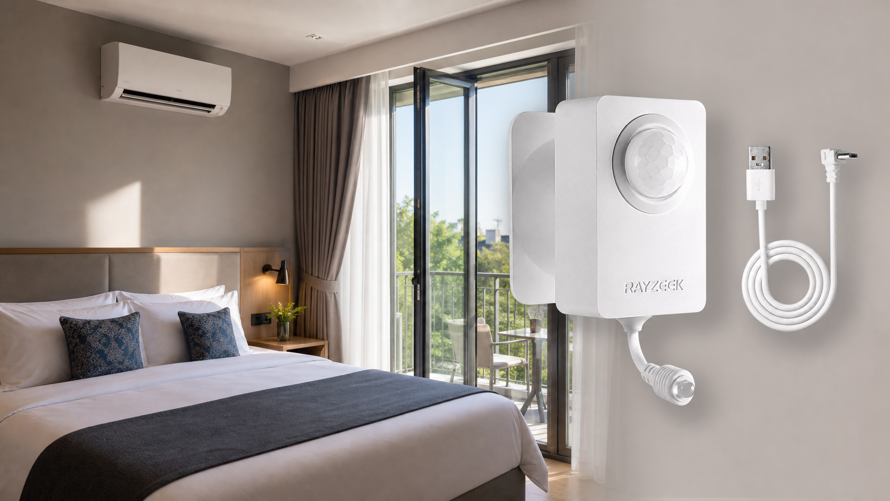
- Wireless motion sensor
- Hardwired control
- Voltage: 2x AAA Batteries / 5V DC (Micro USB)
- Day/Night Mode
- Time delay: 15min, 30min, 1h(default), 2h
- EU plug power adapter
- UK plug power adapter
Overlapping Fields Eliminate Dead Zones

A staggered layout ensures that as a person moves down the corridor, they are never in a detection blind spot. Before they exit the detection cone of the first sensor, they are already entering the cone of the second, which is positioned on the opposite wall further down the path. This overlap is critical. It provides the system with continuous tracking information and enables a smooth, predictive handoff from one lighting zone to the next.
Looking For Motion-Activated Energy-Saving Solutions?
Contact us for complete PIR motion sensors, motion-activated energy-saving products, motion sensor switches, and Occupancy/Vacancy commercial solutions.
Choosing the Right Sensor for Linear Detection
The effectiveness of this layout is enhanced by the choice of sensor. While standard PIR sensors are common, systems that incorporate microwave or dual-technology sensors can offer superior performance in long corridors. Microwave sensors are particularly adept at detecting motion toward the sensor, compensating for a PIR sensor’s primary weakness. In a staggered layout, a microwave sensor aimed down the corridor can detect an approaching person much earlier, providing the crucial data for an anticipatory system.
Pillar 2: Strategic Aiming for Forward-Looking Detection
Placement alone is not enough; the direction each sensor is aimed is just as critical. The common mistake is to mount sensors flat against the ceiling or wall, pointing them straight down or directly across the corridor. This orientation minimizes their ability to detect motion at a distance.
The Role of Sensor Lens and Beam Shape
Every motion sensor has a lens that shapes its detection area into a specific three-dimensional pattern. Understanding this shape is essential for strategic aiming. A long-range lens, for example, creates a narrow, elongated beam designed specifically for corridors. Pairing the right lens with the right placement multiplies the system’s effectiveness. The goal is to project the detection beam as far down the user’s path as possible.
Aiming Ahead of the Path

To achieve proactive detection, sensors in a staggered layout should be angled slightly forward, pointing down the corridor in the direction of travel. A sensor on the left wall should be aimed toward the right side of the corridor further down, and vice versa. This forward-looking orientation casts the sensor’s detection cone far ahead of the user, detecting their approach long before they arrive in that zone. The system is no longer just seeing what is directly below it; it is looking ahead to what is coming.
Pillar 3: Temporal Logic and Pre-Trigger Buffers
The final pillar uses system-level intelligence to connect the geometric and aiming strategies. Even with perfect sensor placement, a small but perceptible delay exists between motion detection and light activation. A truly seamless system eliminates this lag by using pre-trigger buffers. When a sensor detects motion in Zone A, the control system doesn’t just activate the lights in Zone A; it also sends a “pre-trigger” command to the lights in the next logical zone, Zone B.
This pre-trigger can work in two ways. The system can activate Zone B’s lights simultaneously with Zone A’s, ensuring the entire path ahead is instantly illuminated. Alternatively, it can introduce a sub-second buffer, turning on Zone B’s lights just before the user enters, creating a dynamic “wave” of light that moves with them. This temporal logic elevates the system from a series of independent sensors to a single, cohesive network.
Get Inspired by Rayzeek Motion Sensor Portfolios.
Doesn't find what you want? Don't worry. There are always alternate ways to solve your problems. Maybe one of our portfolios can help.
The Complete System: Designing a Seamless Lighting Experience
When these three pillars—staggered spacing, forward aiming, and temporal buffers—are combined, the “chasing the light” problem disappears. The corridor’s lighting system becomes an active participant in guiding the user.
A Walk-Through of the Ideal User Journey

In a properly designed system, a customer entering the corridor is detected by the first forward-aimed sensor. Immediately, the lights in their current zone and the next one ahead activate. As they walk forward, they move through a continuously lit space. The overlapping, staggered sensors track their progress, and the system’s logic continues to activate the next zone in the sequence well ahead of their arrival. Lights behind them turn off after a set delay to conserve energy. The experience is smooth, safe, and feels effortlessly intelligent.
Adapting the Principles for Corners and Alcoves
These principles are adaptable. For a 90-degree corner, a sensor should be placed just before the turn, aimed to detect a person approaching it. This sensor’s primary job is to pre-trigger the lights around the bend, illuminating the new path before the user even sees it. For alcoves or doorways, the main corridor sensors’ wide field of view is often sufficient. The key is to analyze the likely path of travel and place sensors at decision points to always light the way forward.