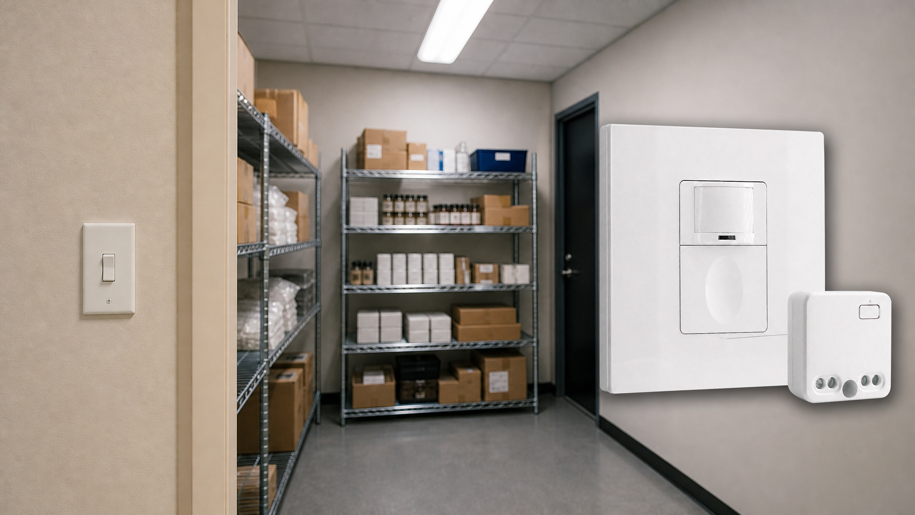
A motion sensor mounted flush to a 16-foot garage ceiling is a recipe for frustration. The lights stay off while someone works near the perimeter. They remain dark as the person crosses the bay. Only when the individual stops directly beneath the sensor does it finally flicker to life. This isn’t a defective unit or a sensitivity problem. It’s a geometry problem.
High-bay spaces like garages, workshops, and storage facilities, with ceilings from 12 to 25 feet, expose a fundamental flaw in how most motion sensors work. The same detection cone that easily covers a floor at eight feet becomes a narrow spotlight at 20 feet. The common response is to crank up the sensitivity, assuming the sensor just needs to “work harder.” This not only fails to solve the coverage issue but also invites a cascade of false triggers from doors, HVAC systems, and even swaying equipment.
The real solution lies in understanding the three-dimensional geometry of detection. It’s about smart placement, the right lens, and multi-sensor zoning. Sensitivity controls the detection threshold, not the coverage area. Your placement strategy is what truly defines that area.
Why Motion Sensors Fail When Mounted Too High
The failure in high-bay installations is predictable. A person enters along a perimeter wall. Nothing. They move to a workbench 15 feet away. Still nothing. They walk across the center of the bay, and only then, after 20 or 30 seconds in the dark, the lights finally come on. The sensor isn’t broken; it’s operating exactly as its detection geometry dictates.
Passive Infrared (PIR) sensors detect motion by identifying temperature differentials moving across segmented zones in their field of view. The lens divides this field into a pattern, and movement from one zone to another registers as an event. These zones project outward from the sensor in a cone. At a standard residential height of seven to nine feet, this cone blankets the floor of a typical room. At 18 feet, that same cone shrinks to a tiny footprint on the floor, often a circle just eight to 12 feet in diameter.
Most motion sensors are engineered for mounting heights between seven and ten feet. Their lens angles and detection algorithms are optimized for this range. A sensor with a 90-degree detection angle might cover a 20-foot-diameter circle at eight feet, but at 18 feet, that coverage shrinks to a 12-foot circle. The entire perimeter of the space—where entry points, workbenches, and storage are—falls completely outside the detection zone.
Get Inspired by Rayzeek Motion Sensor Portfolios.
Doesn't find what you want? Don't worry. There are always alternate ways to solve your problems. Maybe one of our portfolios can help.

This geometric constraint is worsened by another limitation: a dead zone directly below the sensor. At tall mounting heights, this blind spot expands proportionally, further shrinking the effective coverage area.
The Geometry of PIR Detection: How Coverage Cones Work
To understand why height causes failure, you have to visualize how detection zones project into a three-dimensional space. The lens on a PIR sensor isn’t a simple magnifier; it’s an optical tool that carves the sensor’s view into distinct segments. Motion is registered only when a heat signature crosses from one of these segments to another.
Detection Angle and the Shrinking Floor Footprint
A sensor with a 90-degree detection angle creates an expanding cone. While trigonometry suggests that a taller mount should create a wider circle on the floor, practice proves the opposite.
When a sensor is mounted at eight feet, its cone intersects the floor quickly, creating a wide, shallow coverage pattern. At 18 feet, the cone travels much farther down, and its effective field is consumed by vertical space, not horizontal spread. The resulting footprint on the floor becomes much narrower. Furthermore, the outer edges of the cone project at such an extreme angle to the floor that they lose sensitivity. A person walking at the cone’s edge barely registers, if at all.
The relationship isn’t linear. Doubling the mounting height does not simply halve the coverage. The reduction in effective floor coverage accelerates with height. A sensor mounted at 20 feet might only provide reliable coverage over a 10-foot-diameter circle directly below it, leaving 80% of a 30-foot bay invisible.
The Dead Zone Below
Every PIR sensor has a minimum detection distance, a blind spot where it cannot reliably see motion. At a standard eight-foot ceiling height, this might be a negligible one-foot-radius circle on the floor.
At a 20-foot ceiling height, that dead zone can expand to a six or eight-foot radius. This blind spot, combined with the narrowed outer cone, creates a detection area shaped more like a donut than a solid circle. Standing still anywhere might not trigger the sensor, and walking through the space may only produce intermittent detection. This is why simply adjusting sensitivity is a losing battle; the sensor isn’t failing to see, it’s failing to look in the right places.
The Sensitivity Trap: Why Cranking Up Settings Backfires
When a sensor fails to detect motion, the first impulse is to max out the sensitivity. This is based on the flawed assumption that sensitivity controls coverage area. It doesn’t.
Sensitivity adjusts the detection threshold—the minimum temperature change required to register as motion. Low sensitivity requires a bigger, clearer signal. High sensitivity allows the sensor to react to smaller thermal differentials. It doesn’t expand the detection cone or change its geometry; it just lowers the bar for what qualifies as motion within that existing cone.
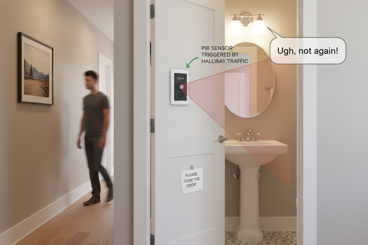
If a person is working 20 feet away, completely outside the sensor’s cone, no amount of sensitivity will make them visible. Instead, high sensitivity makes the sensor vulnerable to false triggers. Workshops are thermally dynamic places. Overhead doors open, HVAC systems kick on, and equipment radiates heat. Hanging tools and cables sway in air currents. With the sensitivity threshold set too low, these non-human events start triggering the lights, which cycle on and off erratically and waste more energy than a manual switch.
The variable to adjust is placement, not sensitivity. The sensor must be positioned so its detection cone actually intersects the areas where people work. This might mean lowering the mounting height, moving from ceiling to wall, or using multiple sensors.
Determining the Right Mounting Height for Your Space
The optimal mounting height for a sensor in a high-bay space is a balance between ceiling height, room dimensions, lens type, and workflow. The goal is to get the sensor low enough for a wide floor footprint but high enough to avoid obstruction.
Ceiling Height vs. Sensor Placement
- 12 to 15 feet: Ceiling mounting can still work here, especially with a wide-angle lens. A sensor with a 110-degree detection angle mounted at 12 feet can cover an 18 to 22-foot diameter circle, sufficient for many single-car bays.
- 16 to 20 feet: Ceiling mounting becomes marginal. A sensor at 18 feet may only cover a 12-foot circle, which is inadequate for a 24-foot-wide bay. In these cases, consider mounting the sensor lower on a column or beam, or use multiple sensors for overlapping coverage.
- Over 20 feet: Standard ceiling-mounted sensors are generally unsuitable. The best approach is wall mounting at a height between eight and 12 feet, allowing the sensor to look across the floor plane instead of straight down.
To estimate coverage, you can use a rule of thumb. Calculate the theoretical diameter based on the sensor’s detection angle and height, then reduce that number by 25-30% to account for real-world limitations like the dead zone and reduced sensitivity at the edges.
Wall Mounting as an Alternative

Wall mounting offers a completely different geometric advantage. Instead of projecting a cone downward, the sensor projects it horizontally, detecting movement as a person crosses its field of view. This orientation uses the cone’s width to cover the floor, not the air.
A sensor mounted on a wall at ten feet, angled slightly down, can reliably cover a 20 to 30-foot range. The trade-off is a directional bias; it will be better at detecting movement toward or away from it than parallel to it. In long, narrow bays, this is often perfect. In wider spaces, you may need sensors on opposing walls. The optimal height is typically eight to 12 feet—high enough to clear obstacles but low enough to maintain an effective angle on the floor.
Maybe You Are Interested In
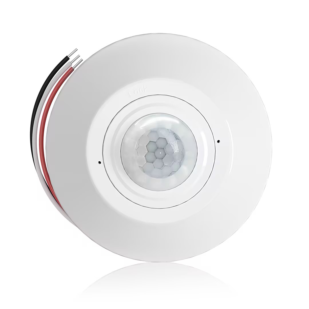
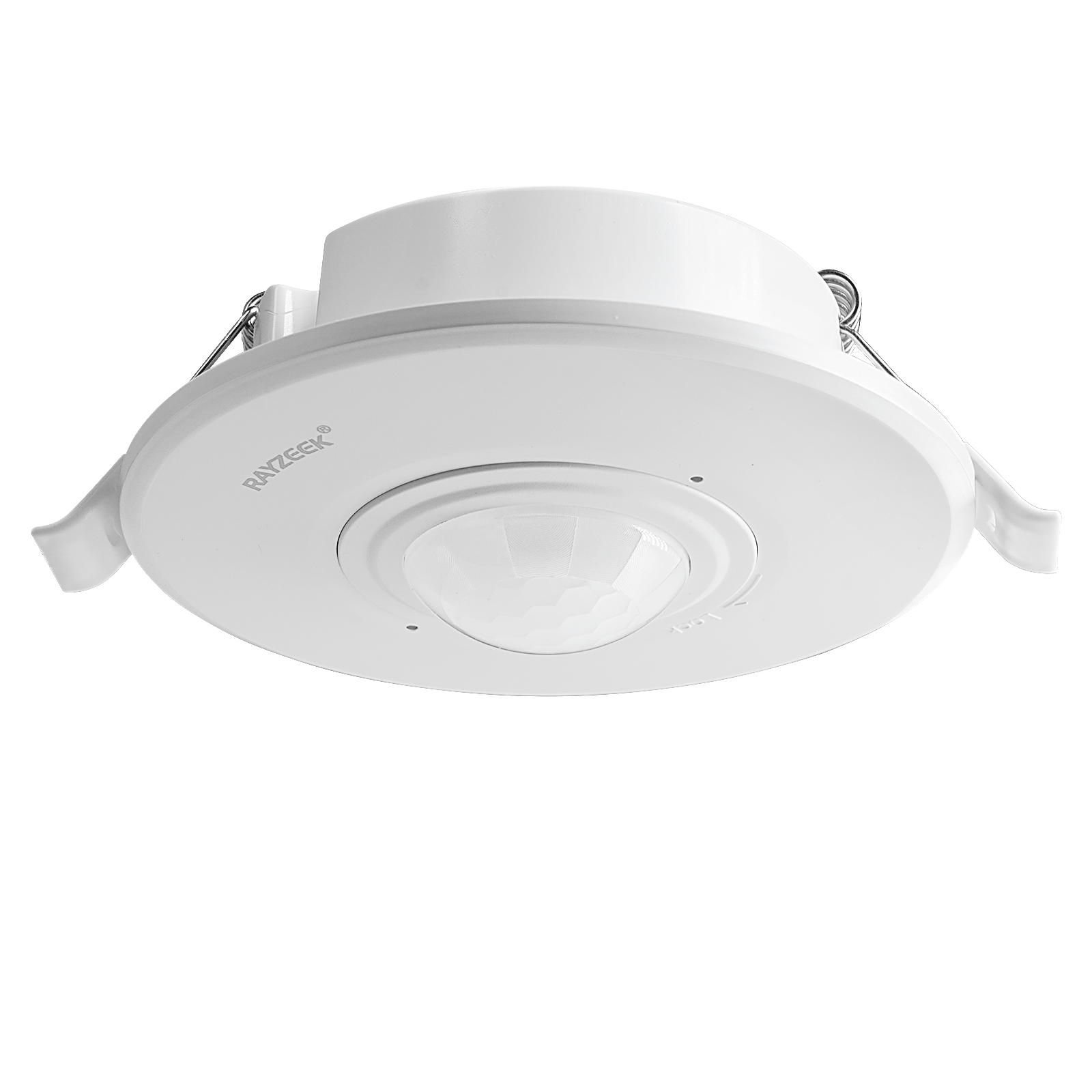
- Ceiling-mounted PIR occupancy sensor with dry-contact relay output
- 12/24VDC or 12/24VAC low-voltage supply
- COM, NO, and NC isolated relay contacts for EMS, HVAC, and building control inputs
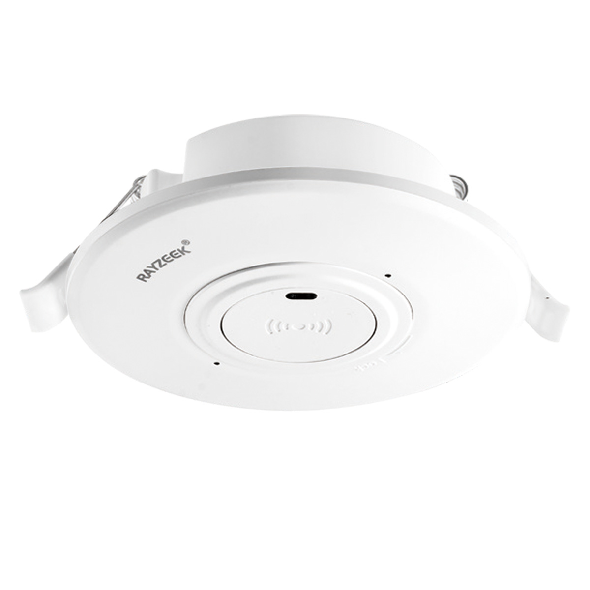
- Low-voltage DC recessed ceiling-mounted microwave motion sensor switch
- 12 VDC / 24 VDC input with 10-30 VDC range
- 10A max work current with adjustable time delay, Lux threshold, and sensitivity
- Higher-load recessed ceiling-mounted microwave motion sensor switch
- 100-265 VAC line-voltage input, 10A model
- 5.8 GHz microwave sensing with adjustable time delay, Lux threshold, and sensitivity
- Recessed ceiling-mounted microwave motion sensor switch
- 100-265 VAC line-voltage input, 5A model
- 5.8 GHz microwave sensing with adjustable time delay, Lux threshold, and sensitivity
- Ceiling-mounted RZ037 PIR occupancy sensor dimmer for 220V power
- 3A maximum working current with 660W rated load
- LUX button controls light-sensor ON/OFF and user-set dimming brightness
- Ceiling-mounted RZ037 PIR occupancy sensor dimmer for 110V power
- 3A maximum working current with 330W rated load
- LUX button controls light-sensor ON/OFF and user-set dimming brightness
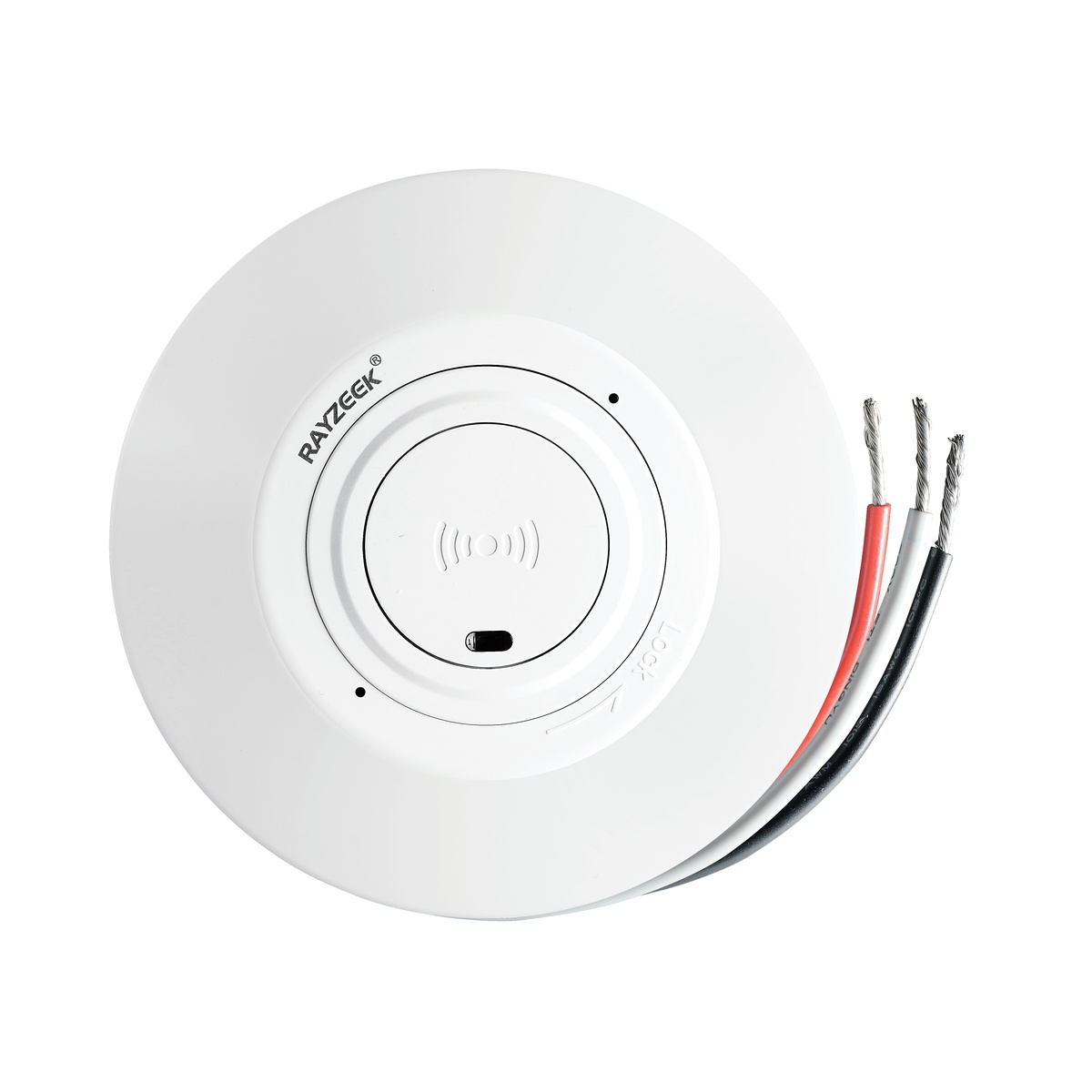
- Low-voltage DC ceiling-mounted microwave motion sensor switch
- 12 VDC / 24 VDC input with 10-30 VDC range
- 10A max work current with adjustable time delay, Lux threshold, and sensitivity
- Higher-load ceiling-mounted microwave motion sensor switch
- 100-265 VAC line-voltage input, 10A model
- 5.8 GHz microwave sensing with adjustable time delay, Lux threshold, and sensitivity
- Ceiling-mounted microwave motion sensor switch
- 100-265 VAC line-voltage input, 5A model
- 5.8 GHz microwave sensing with adjustable time delay, Lux threshold, and sensitivity
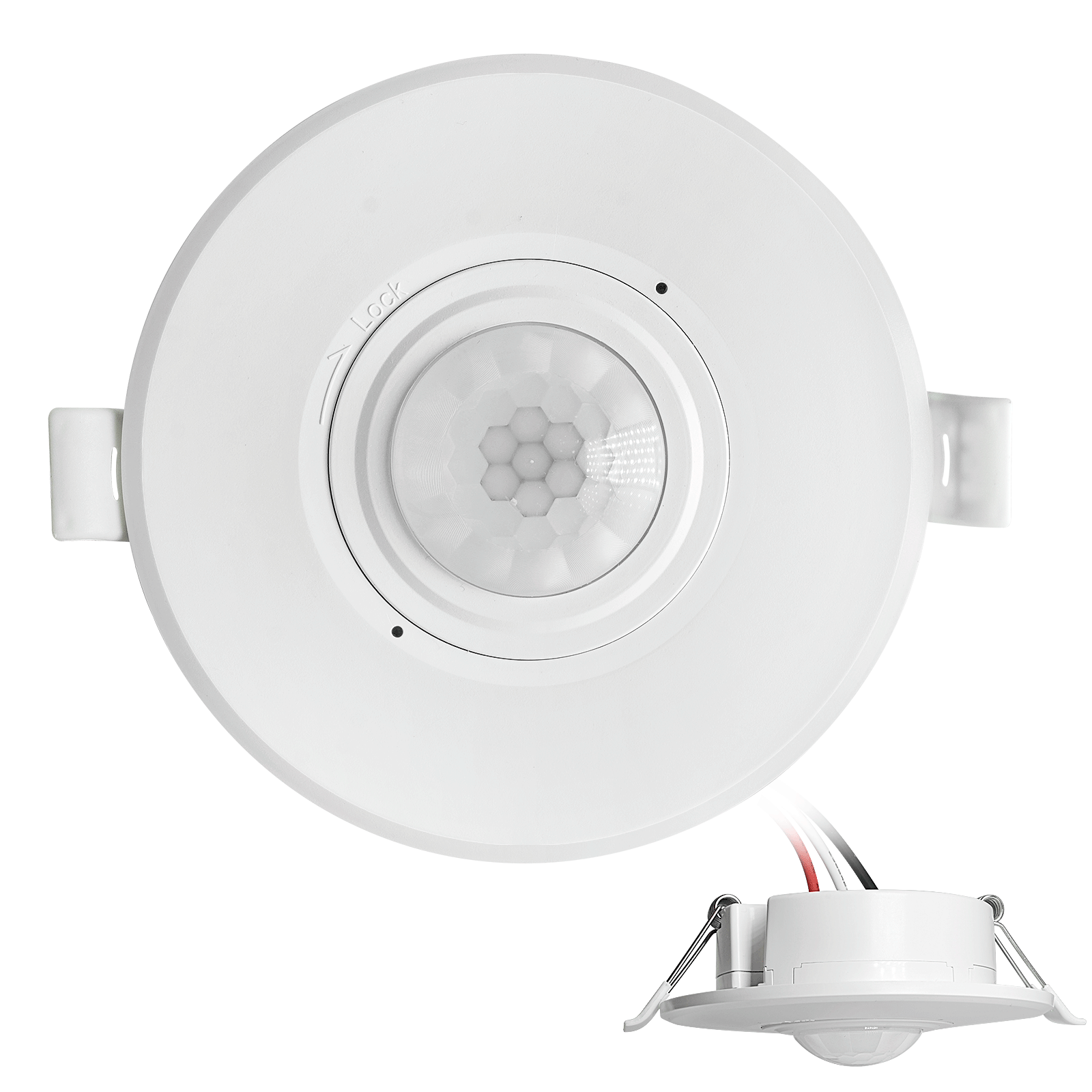
- Low-voltage DC recessed ceiling mount PIR motion sensor switch
- 12 VDC / 24 VDC input with 10-30 VDC range
- Max work current 10A with adjustable time delay, Lux threshold, and sensitivity
- Higher-load recessed ceiling mount PIR motion sensor switch
- 100-265 VAC line-voltage input, 10A model
- 360-degree detection with adjustable time delay, Lux threshold, and sensitivity
- Recessed ceiling mount PIR motion sensor switch
- 100-265 VAC line-voltage input, 5A model
- 360-degree detection with adjustable time delay, Lux threshold, and sensitivity
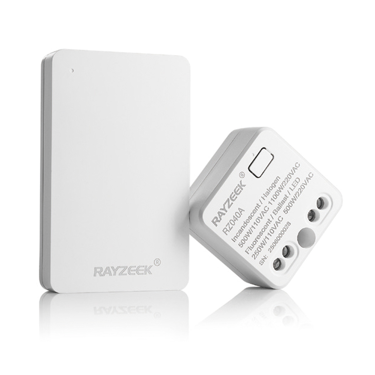
- Wireless switch and receiver kit for indoor ON/OFF lighting control
- 100-230VAC, 50/60Hz receiver with 5A rated current
- CR2032-powered wireless switch with 2.4GHz communication
- Occupancy (Auto-ON/Auto-OFF)
- 12–24V DC (10–30VDC), up to 10A
- 360° coverage, 8–12 m diameter
- Time delay 15 s–30 min
- Light sensor Off/15/25/35 Lux
- High/Low sensitivity
- Auto-ON/Auto-OFF occupancy mode
- 100–265V AC, 10A (neutral required)
- 360° coverage; 8–12 m detection diameter
- Time delay 15 s–30 min; Lux OFF/15/25/35; Sensitivity High/Low
- Auto-ON/Auto-OFF occupancy mode
- 100–265V AC, 5A (neutral required)
- 360° coverage; 8–12 m detection diameter
- Time delay 15 s–30 min; Lux OFF/15/25/35; Sensitivity High/Low
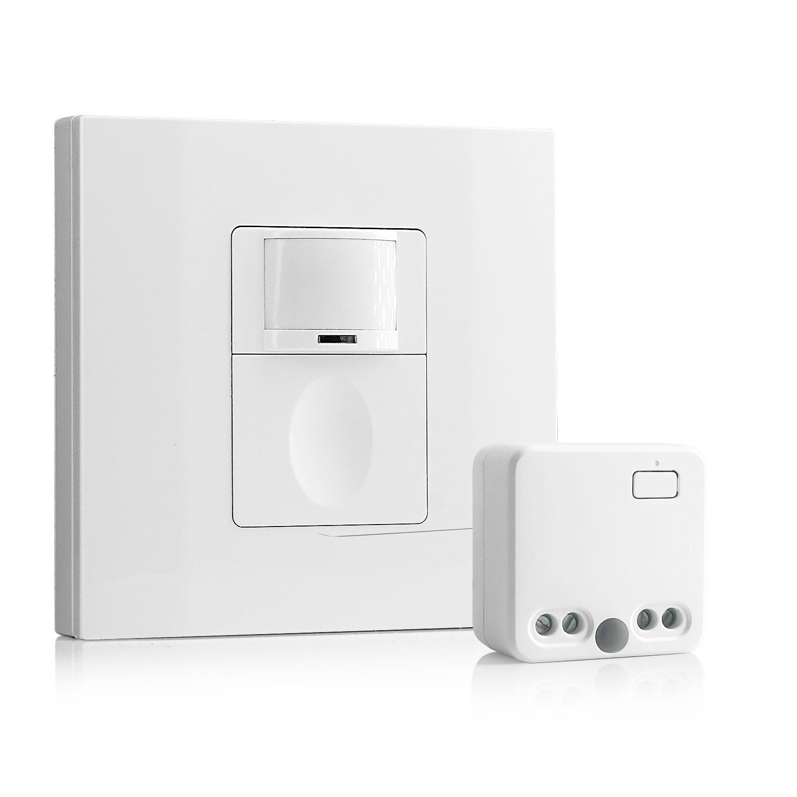
- 100V-230VAC
- Transmission Distance: up to 20m
- Wireless motion sensor
- Hardwired control
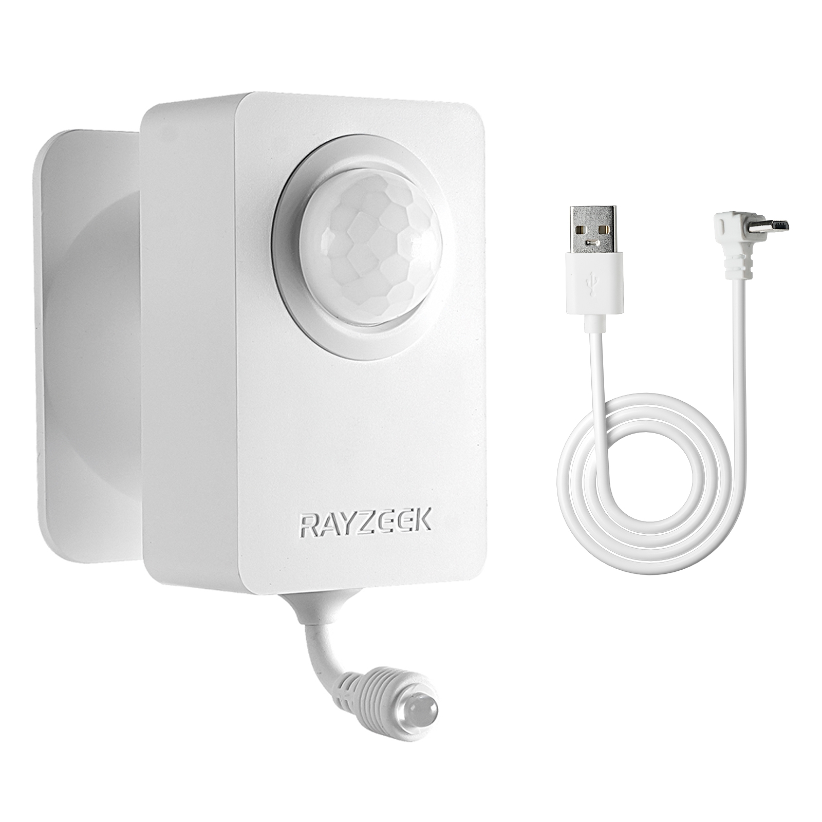
- Voltage: 2x AAA Batteries / 5V DC (Micro USB)
- Day/Night Mode
- Time delay: 15min, 30min, 1h(default), 2h
- EU plug power adapter
- UK plug power adapter
Lens Selection Strategy for Tall Spaces
The lens dictates a sensor’s coverage geometry. In high-bay applications, it’s a critical choice between wide-angle and narrow-angle options.
Wide-angle lenses (110-180 degrees) are the default for ceiling mounts in moderately sized bays, designed to cover a broad floor area from a single point. Their trade-off is a shorter effective range. At greater heights, the edges of a wide-angle cone become too shallow and lose sensitivity.
Narrow-angle lenses (60-90 degrees) focus the detection cone into a tighter, longer-range beam. A 60-degree lens can detect motion 40 feet away or more, making it ideal for long, narrow bays or wall-mounted applications. Its trade-off is reduced side-to-side coverage, creating blind spots in a wide room unless multiple sensors are used.
The choice depends on the room’s shape. For square bays with moderate ceilings (12-16 feet), a wide-angle lens on the ceiling works well. For long, narrow bays, narrow-angle lenses on the end walls provide superior coverage. For very tall ceilings (18+ feet), wall-mounted narrow-angle sensors are often the only reliable single-sensor solution.
Multi-Sensor Zoning for Complete Coverage
For large or complex spaces, a single sensor will always have limitations. The professional approach is multi-sensor zoning, which uses a coordinated array of sensors to create complete, overlapping coverage.
Calculating Coverage Overlap

Instead of trying to stretch one sensor’s range, deploy two or more with overlapping detection zones. This ensures a seamless transition as a person moves through the space. The industry standard is to design for 30-50% overlap. If a sensor has a 20-foot effective diameter, the next sensor should be positioned no more than 13 feet away. This guarantees that any point on the floor is covered by at least one sensor, eliminating gaps.
Addressing Corners and Obstacles
Even with proper spacing, corners and large objects create dead zones. A sensor’s view is a straight line; it can’t see around a support column or through a vehicle on a lift. The solution is targeted supplemental coverage. A small, dedicated sensor placed in a corner or on the far side of an obstacle can eliminate these shadow zones without disrupting the primary layout.
Zoning isn’t about adding more sensors; it’s about strategic placement. A well-designed system provides uniform coverage and reliable detection because each sensor operates within its optimal range and sensitivity.
Looking For Motion-Activated Energy-Saving Solutions?
Contact us for complete PIR motion sensors, motion-activated energy-saving products, motion sensor switches, and Occupancy/Vacancy commercial solutions.
Placing Sensors to Avoid False Triggers
The final step is positioning sensors to ignore the normal thermal and mechanical activity of a workshop. This is about placement, not turning down sensitivity.
Thermal Interference: Position sensors so their cones do not intersect the airflow from forced-air heaters or HVAC vents. Keep them angled away from large overhead doors, which introduce rapid temperature shifts when opened. If a door must be in the detection area, a short time delay on the sensor’s output can filter out the transient event.
Moving Objects: Mount sensors where swaying cables, hoses, or hanging tools are stationary relative to the sensor’s field of view. A sensor mounted directly above a hanging air hose won’t see it as motion, even if it sways.
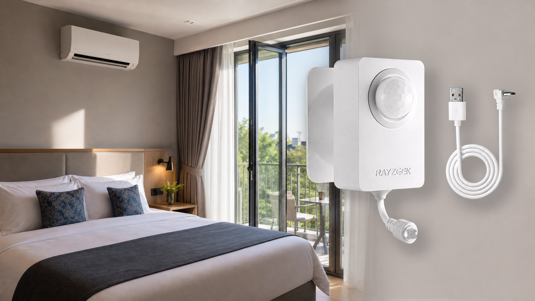
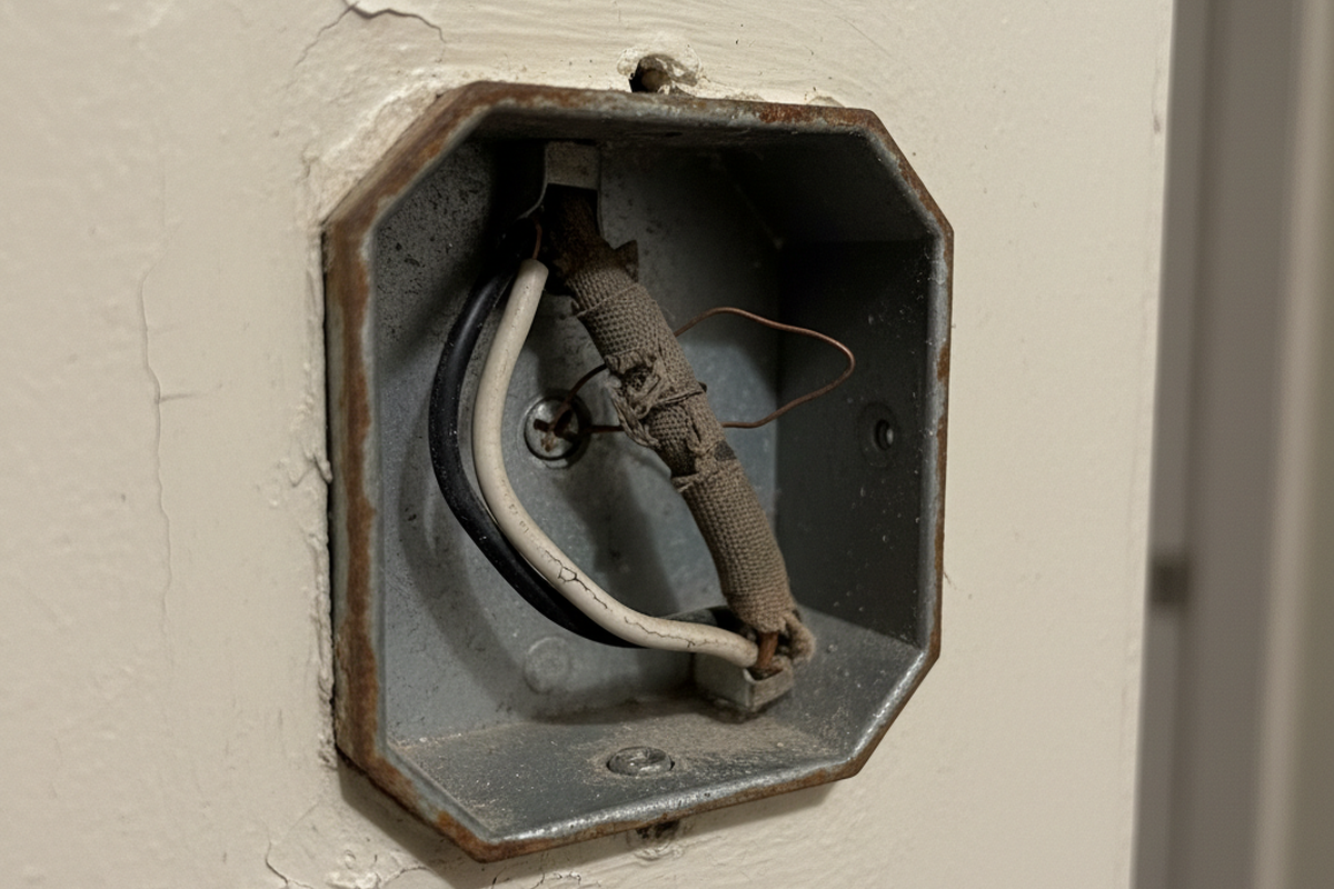
Wireless sensors offer far more flexibility for this kind of strategic placement, as they aren’t constrained by existing conduit. Whether wired or wireless, the strategy is the same: use placement, angle, and lens type to solve both detection gaps and false triggers, leaving the sensitivity setting at its manufacturer-recommended level.